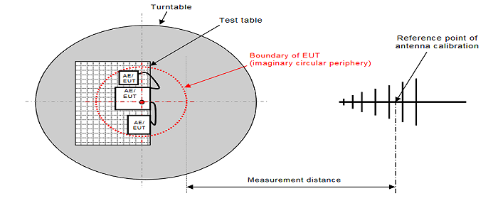
As a part of performing EMC (Electromagnetic Compatibility) tests, test facilities measures radiated/conducted EMI generated from the product. These measurements of the electromagnetic field is the search of emissions that are unintentionally being generated by the equipment under test. So here will be a walkthrough “How to” EMI tests are performed:
Definitions:
EMC – Electromagnetic Compatibility – The ability of a product to operate (compatibility) within different electromagnetic environments.
EMI – Electromagnetic Interference – The amount of electromagnetic emissions (interference), either radiated or conducted, coming from a product.
EUT – Equipment Under Test.
Radiated Emissions – A measurement of the over-the-air interference emitted from a EUT, from both the enclosure (often called the enclosure-port) or the cabling. Limits typically expressed in terms of Volts per meter (dBµV/m) for electric field, or Amperes per meter (dBµA/m).

- Place the antenna at the proper distance from the source of the emissions, or the equipment under test. Typically this distance would be a 3, 10 or 30 meter separation depending on the test standard.
- Connect the output of the receiving antenna to input of the spectrum analyzer usually it is a fairly long cable in between the antenna and the receiver so a good point is to keep the VSWR and losses as low as possible. The input impedance for the receiving system, and the receiving antenna should all be matched to 50 Ohm. If this is not the case, the readings will require some type of correction table for the impedance mismatch.
- Ensure that the receiving antenna is capable of providing accurate measurements at that frequency. Sometimes a change of antenna is necessary.
- The measured RF voltage \large { V }_{ a } should be in decibels referenced to 1 micro-volt dBmV. The conversion factor are as follows: Va\left( dBmV \right) =20*\log _{ 10 }{ \left[ Va\left( mV \right) \right] }
- Next step is to add the antenna factor AF to determine the fieldstrength. The antenna factor should be provided of the manufactor.
- When the measured result is presented all devices in the signal path such as pre-amplifier (gain), cable loss and RF switches (attenuators) that is used in the system be incuded.
{ E }_{ a }(dBmV/m)={ V }_{ a }(dBmV)+AF(dB/m)+Cable(dB)+PreAmp(dB)

