
The efficiency of an antenna is the ratio of the power delivered to the antenna relative to the power radiated from the antenna. And this property goes either for the antenna if it is in receiving or transmitting mode.
- A low efficiency antenna has most of the power absorbed as losses within the antenna, or reflected away due to impedance mismatch.
- A high efficiency antenna has most of the power present at the antenna port radiated away.

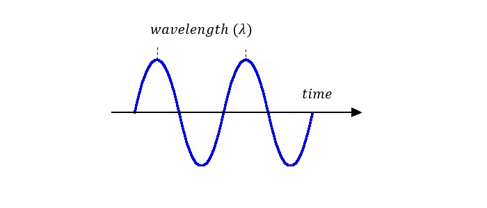
Frequency & Wavelength:
Frequency f is simply the number of complete cycles the wave completes in one second, ex: 400 cycles per second is written 400 Hertz. Mathematically this is written as:

Basically, the frequency is just a measure of how fast the wave is oscillating.
- The faster it oscillates the shorter the wavelength.
- Longer wavelength implies a slower frequency

Think of when you were a child and you used the magnifier to focus the suns sunlight to burn a spot on the grass. The same priciple goes for the directivity for an antenna. It is a measure of how focused an antenna coverage pattern is in a given direction. A theoretical loss-less antenna element, referred to as a isotropic element, has 0 dBi directive gain equally distributed in all 3 dimensions. In order to achieve higher directive gain, antennas are normally designed to focus or concentrate the antenna pattern only in the direction of the radio link, thereby maximizing energy usage.
Antenna Factor:
The Antenna Factor (AF) is defined as the ratio of the incident Electromagnetic Field to the output voltage from the antenna.

Antenna:
An antenna is an resonant devices that transmits and/or receives electromagnetic waves. The antenna is resonant over a frequency spectrum and it is over this spectrum one say that the antenna is oprating in a radio system.
Isotropic Radiator:
A theoretical source point that radiates uniformly in all directions over a sphere centred on the source.
Antenna Gain:
Describes how much power is transmitted in the direction of peak radiation to that of an isotropic source usually expressed in dB.
Example; A transmitting antenna with a gain of 3 dB means that the power received far from the antenna will be 3 dB higher (twice as much) than what would be received from a lossless isotropic antenna with the same input power. Antenna Gain can be related to directivity and antenna efficiency by:

Field Regions:
Field surrounding an antenna are divided into 3 regions:
- Far Field or Fraunhofer Region
- Reactive Near Field
- Radiating Near Field or Fresnel Region
In this region the radiation pattern does not change shape with distance and the E- and H-fields is orthogonal to each other and the direction of propagation as with plane waves. The field die off as 


 (much much greater than) often satisfies that the left side of the sign is teen times bigger.
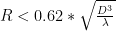
Reactive Near Field Region:
In this region the E- and H- fields are out of phase by 90 degrees to each other “For radiating fields, the fields are perpendicular but are in phase”. The boundary of this region is commonly given as:
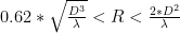
Radiating Near Field (Fresnel) Region:
In this region, the reactive fields are not dominate; the radiating fields begin to emerge. The region is commonly given by:
Polarization:
The polarization of an antenna is the polarization of the radiated fields produced by an antenna, evaluated in the far field. Antennas are often classified as:
- Linear polarization
- Right Hand Circularly Polarized
For two linearly polarized antennas that are rotated from each other by an angle 

what if a circular polarization antenna will transmitt to a linearly polarized antenna or vice versa? Circular polarization is two orthongal linear polarized waves 90 degrees out of phase. The linearly polarized antenna will only pick up the in-phase component. So the linear polarized antenna will have a polarization mismatch loss of 0.5 “-3dB”. So: